
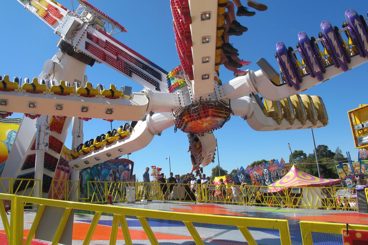
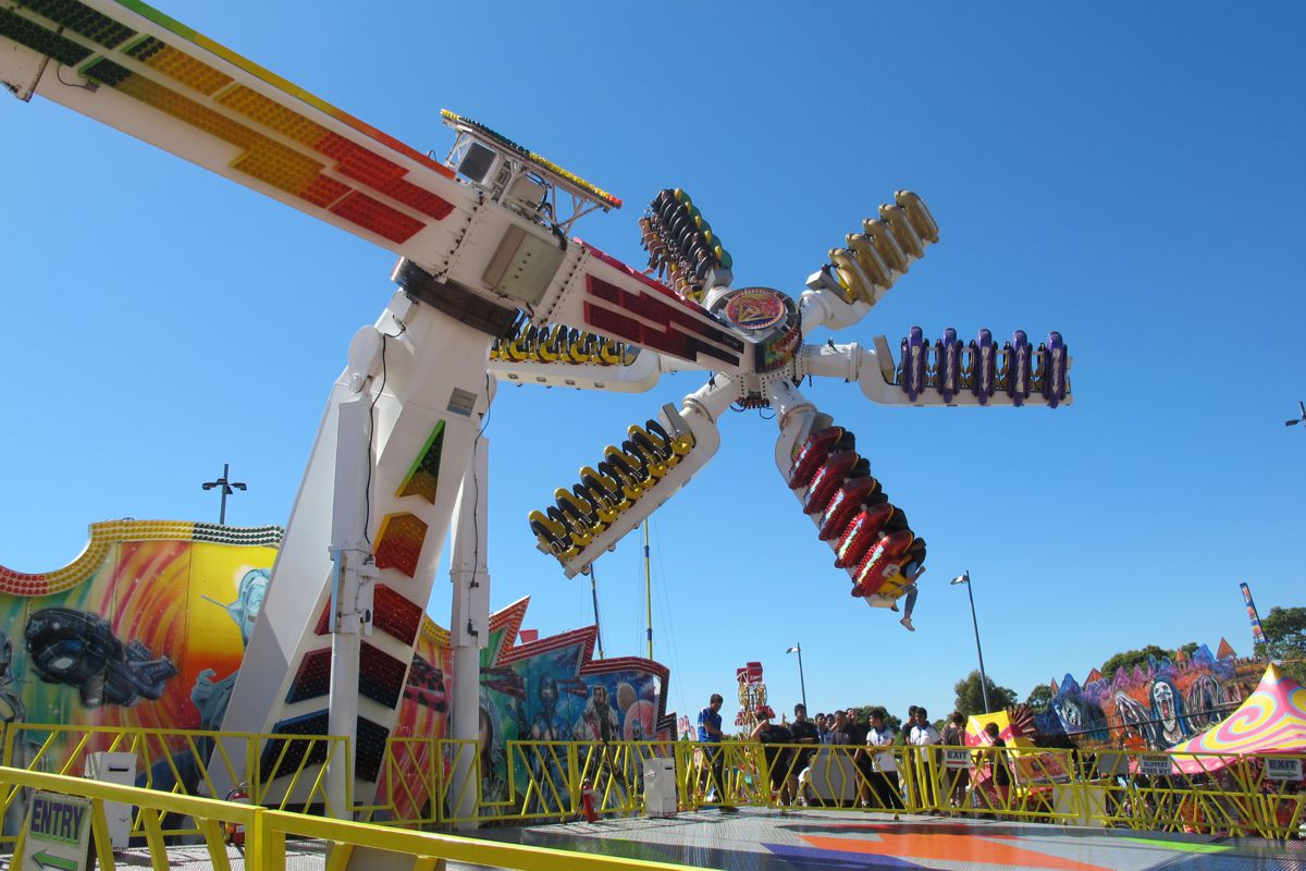
Also known as the Top Scan, the Spaceroller is an amusement ride made by Mondial based in the Netherlands. It comprises 6 free-rotating gondolas each with 5 seats & the standard Mondial triple-lock harnesses which includes a redundancy safety belt! PLEASE DOWNLOAD the Spaceroller Operations Manual and READ it thoroughly.
TECHNICAL DESCRIPTION OF OPERATION
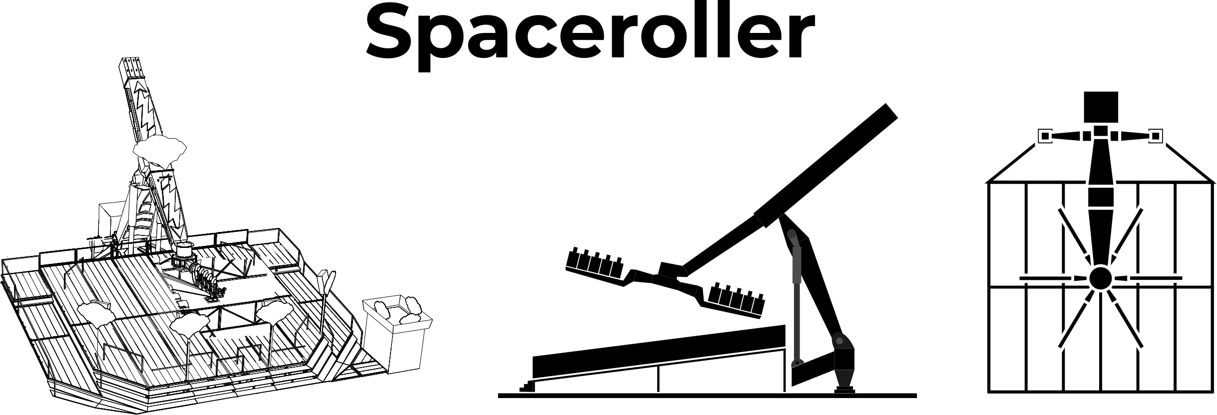
This ride consists of a main mast with a drive on which an arm is mounted in an angle of approximately 45 degrees to the mast. The variable hydraulic drive enables the main arm with the gondolas to rotate to the left and to the right. The gondola cross which is assembled in a star form, consists of six gondola arms, upon which five suspended seats are mounted and equipped with the Mondial “triple lock” Super Restraint System. The gondola cross rotates to the left or to the right and is driven hydraulically. The gondolas are allowed to move freely using centrifugal force. The platform is static, the main mast lowers to load and unload the gondolas. Two hydraulic cylinders are used to move the mast up or down, it will lift in 10 seconds. The platform is equipped with fences and the special TOPStep® anti skid aluminum profile.
The ride is provided with a system control panel. The operations of the main arm and gondola cross are limited for over speed. The restraints are monitored during the ride cycle. On each gondola an operator panel is mounted to open and close the restraints; every seat has its own light that indicates that the restraint is closed. The ride is provided with an automatic parking system to put the arm in zero position and lower the mast automatically.
The seats and the restraint are made of black PUR foam on a solid metal frame, shaped in a way that it is suitable for a wide range of body profiles. Every seat is equipped with the Mondial “triple lock” Super Restraint System. The restraints are double locked mechanically and blocked hydraulically. The restraints open and close pneumatically. During the ride cycle the restraints are monitored. During loading and unloading the arm safety brake is activated to prevent movement caused by unequal loading.
In case of a power failure an emergency battery can be used to operate the drive. There is no upper height limit but the passenger has to sit straight and the restraint has to be closed tight to the body. For checking the minimum height, measuring devices need to be available at the entry of the ride. Passengers need to have natural upper legs including the knees.
Passengers with spinal complaints, high blood pressure, heart problems, pregnant women and persons under the influence of alcohol, drugs, medications or other narcotics may not ride on the Spaceroller.
At the ride, safety warnings have to be placed. This is the responsibility of the operator. Before the passenger takes a seat on the gondola, he or she has to remove from their person any loose objects, such as bags, scarves and other objects. These objects may be put on the edges of the platform of the Spaceroller. Domestic pets are also barred from the Spaceroller.
When the passenger takes a seat, he or she has to sit properly in the seat with the back fully supported. The passenger has to place one leg on each side of the pommel protuberance (node). The passenger has to place hands and arms around the (seat) restraint so that the restraint is properly positioned against the body. (See appendix A2 figure 1) The passenger has to put his hands on the handgrips of the restraint.
The operating staff has to ensure that the passengers are safely seated, and they have to check every restraint individually by pushing and pulling to check if it is tight against the body and to check if the restraint is hydraulic and mechanical locked.
The operating staff has to ascertain that the Spaceroller can safely operate. They also have to ensure that no persons or animals are within the safety fencing while the Spaceroller is operated.
COMPREHENSIVE INSTRUCTIONS
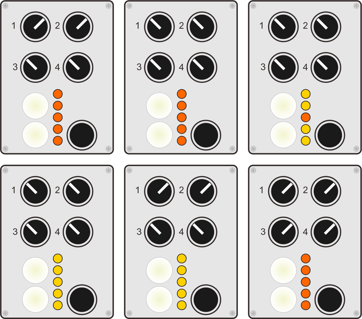
Comprehensive Instructions on how to load and unload passengers from the Spaceroller are supplied going into specific detail (with drawings) on how to use the Gondola Control Box (illustrated left).
All ASA Spaceroller employees must be familiar with the Spaceroller Gondola Control box function.
The correct loading and securing of passengers is paramount to the safe operation of the Spaceroller.
In addition to this, All Employees will be taught what to do during an Emergency Situation.
ASA Spaceroller Employees will be instructed and provided documentation relating to EMERGENCY PROCEDURES. These encompass an Emergency Stop, signaling an Emergency Stop and actions required to take during a Power Failure.
This information is provided to our employees and must be signed for as read and demonstrably understood before employment begins.
EMPLOYEE RESPONSIBILITIES
It’s an employees responsibly to patrons to maintain 100% eyes on and audio vigilance on the ride at all times so that if something goes wrong they are in a position to call in an emergency stop to the ride.
This means that use of mobile devices, eating and drinking or casually chatting to passers by during the operational cycle of the ride is strictly forbidden and enforced.
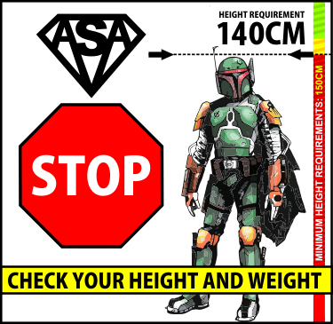
Staff are also aware that Riders must be at least 140cm tall to ride the Spaceroller. This is to ensure that the safety harness will fit securely.
If the staff member is not sure that a rider is 140cm tall, they must check them against the minimum required height signs that we have at the loading gate entrances.
SAFETY DURING OPERATION
1 The ride parameters set at the final inspection, such as acceleration speed, maximum speed, etc. may not be altered!
2 During operation the operator position needs to be constantly occupied by a trained, skilled, person.
3 During the ride sequence no personnel or public may be present in the danger zone (inside the perimeter fence).
4 At least 1 member of staff must be present at the entry and exit gate.
5 When the passengers take their places, the staff must ensure that the passengers are sitting properly with their back fully supported and that they have a leg on either side of the pommel protuberance (node). The staff also has to supervise that the restraint is positioned tight against the body, after closing the restraints. No objects may be present between body and restraint like bags, folded clothes etc. Finally the passengers have to grasp the handgrips around the restraint.
6 The operating staff shall observe the ride and the passengers constantly.
7 People smaller than 1.4 meters (55 inches) and/or younger than 12 years and people that don’t have natural upper legs and knees may not ride the Spaceroller.
8 People with spinal complaints, high blood pressure, heart problems, pregnant women and persons under the influence of alcohol, drugs, medications or other narcotics may not ride the Spaceroller.
9 Loose objects as bags, hats / caps, glasses must be taken off (and put on the platform)
10 The directions 7,8 and 9 have to be made clear to passengers by means of signs at the entry of the ride and by verbal instructions form the attendant.
SPACE ROLLER EMERGENCY EVACUATION PROCEDURES
In the unlikely event of an emergency our staff will need to know what to do in their role as an ASA ride attendant.
We teach you that it is important to remain calm. Even if they do not know what has happened they know that a Senior ASA manager will be on board to correct the issue and their role is to re-assure the crowd to remain calm and to let them know that they will not be waiting long. We also teach them that if they see or notice something, they must notify the control attendant if they are not aware of any unusual activity. This could be an ususal noise or sound that has come from the ride, falling lights or caps from the boom or a flying article that the patrons have not secured in their pockets.
We instruct you that they can never be too cautious so do not hesitate to notify their manager in control.In the event that the ride stops and patrons are on the ride. We teach them not to panic and to make sure their team members are calm as well. They are instructed to remain at their post and do move around the deck under the ride swing.
You can re-assure the patrons in the line that its a small technical issue that will be resolved quickly. If they are not required by a senior staff member they can remain at their post and continue to talk with the patrons, to make them feel calm and unworried. In the event of a power failure, we have a backup generator and our senior staff know the procedure to bring the Spaceroller safely down where our staff can quickly assist with the unloading of patrons.
EMERGENCY STOP
If a perilous situation occurs for passengers, public or the Topscan during the ride, the button “emergency stop” should be pressed and the Topscan will stop as fast as possible. The emergency stop command can be given from the control cabin by the main operator. (located on main control panel) When the ride has come to rest, first the emergency situation has to be resolved. The Topscan can be started again after the emergency stop has been reset:
To reset, turn the emergency stop button on which it “jumps out” and the reset failure button. The Topscan also carries out internal checks. If a malfunction appears, the Topscan performs an (emergency)stop by itself.
POWER FAILURE
With a total of 6 staff on the Deck including 1 Controller & 1 Manager, 4 staff will be placed at each exit gate talking to the crowd.
1 Controller will be in the Control Booth & 1 Manager on ground assessing with 2 attendants to assist.
If the main power supply fails, but there is still power from another power supply available the gondolas are brought back to the embarkation position with an emergency aggregrate (Appendix A2 Fig 9)
Connect the aggregate to the alternative power supply.
- Close valve 1 & 7. Open Valves 3,4 & 5.
- Start up aggregate
- Use valve on aggregate to bring the arm & the gondolas to the O position.
Once the gondolas are at the O position, connect the manual pump to the main lift cylinder. (Appendix A2 Fig 10) & close Valve 9.Pressure up until the gondola and arm starts to lower.
For the disembarking of passenger’s the restraints can be opened using the emergency batteries.
Connect the emergency cable between the emergency batteries and the gondola. To disembark, follow the regular procedure.
After the passengers have disembarked from the gondolas, turn off the emergency aggregate. Set the Valves 1, 2, 3, 4, 5, 7 & 9 back to their original positions and restore the main power supply.
TRANSPORT AND ERECTION
The Spaceroller is transported on at least two transports. 1 Trailer integrated in the Spaceroller containing the mast, the arm, the chassis, the main drive and the supports and 1 transport containing the gondolas and the platforms etc.
For erection of the Spaceroller, the following equipment is necessary:
- Hoisting crane +- 25 tons metre
- Hoisting equipment such as D-shackles, belt slings, 2 tandem hops, 4 tooth –hops.
- Tools such as closed end spanners/wrenches, torque wrenches, levels, laser length meters.
ERECTING THE SPACEROLLER
Valves named in paragraph 3.1 and 3.2 are named in appendix A1 drawing 115-05-246 or 247 and their location is shown in appendix A2 figure 2 Manoeuvre the middle construction (trailer) into the correct location. Fit the front and rear supports. Place the wooden prop boards and support plates underneath the ends of the supports and adjust to the correct height (see Appendix A1 drawing 115-05-384). Now allow the middle construction (trailer) to lower onto the support plates.
Raise the mast slightly with the remote control (appendix A2 fig. 4), after turning valve no.8 into ‘set up’ position, using the hydraulic cylinders, so that the working platform can be fitted onto the arm. Now raise the mast fully. The gondola arm is now pulled up slightly using a mobile crane or similar, a steel cable and a snap block (roller), so that the bolt used to fixate the gondola arm to the mast can be removed. Now pay out the cable until the gondola arm hangs freely. The mast can be lowered slightly. The steel cable is now pulled in such a way that the flange of the gondola arm is pulled against the flange of the hub. Now place a ladder on the gondola arm and fit at least four bolts on the front in order to fasten the flanges.
Open valve no.6 of the hydraulic unit so that the gondola arm can move freely. When turning the gondola arm using the mobile crane the brake must be released. To release the brake see 5.1. Turn the gondola arm and the hub through 90 degrees using the crane and then lower the mast again. Allow the end of the gondola arm and hub to rest on a frame.
Fit the counter-arm and, after closing by-pass valve no.6, raise the mast again. The hydraulic lifting cylinders now need to be locked mechanically by turning the locking discs and fasten them. Turn the gondola arm with the hub to 180 degrees so that the counter-arm is at the bottom. Fit a 3.8 T counterweight. Turn arm and hub back to 0degrees and fit two gondolas. The further sequence of assembly is 2.5 T counterweight > 2 gondolas > 3.7 T counterweight > 2 gondolas > 2.5 T counterweight. A torque wrench is necessary up to 750 bar placed on the bolt side.
Put valve no 8 into ‘operation’ position.
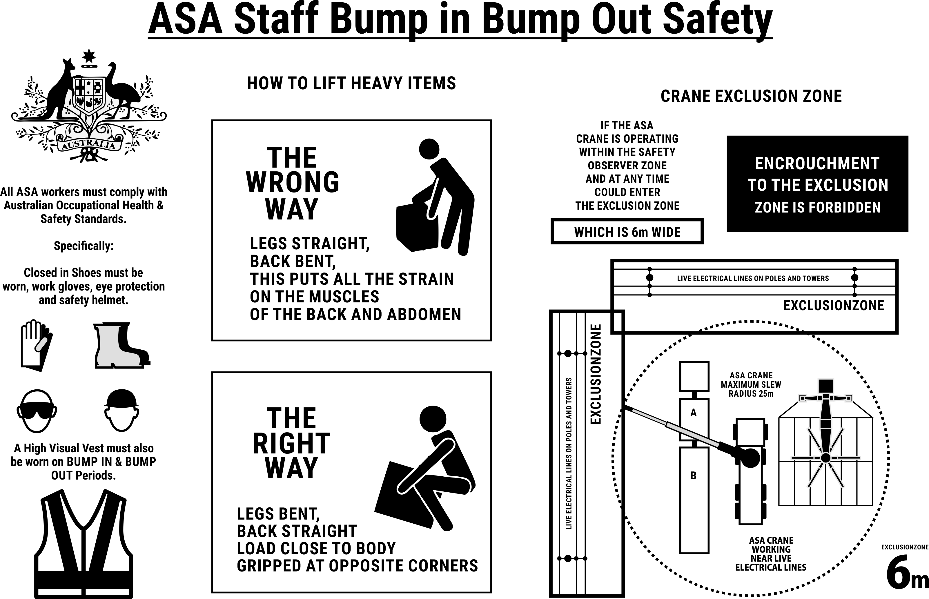
When erecting the Spaceroller & Platform please familiarize yourselves with the
Crane Safety Zones and Lifting of Heavy Items Instructions below:
CONSTRUCTING THE PLATFORM
See drawings of the platform appendix A2 figure 3.
Place the part of the support, indicated on the drawing by ‘Mark 1’, which is beside the frontsupport legs, on the appropriate stays at the chassis. Lock this part of the support using two‘Mark 1’ struts which run towards the chassis.
Suspend support parts, Mark 2 and 3, on both sides of support, part Mark 1 and prop up with wood in such a way that it is exactly horizontal (for propping up see drawing 115-05-276). Also fit struts Mark 2 as well as Mark 3 and Mark 4 between support part Mark 2/3 and the chassis. Hook in support part Mark 11 and 12 (mirror image) to the frame Mark 2 and 3. Prop these up until they are horizontal.
Fit support part Mark 4 using strut Mark 5 and adjust to the correct height. The underside of the support part is to be at the same height as the underside of support part Mark 2 or 3. Now fit auxiliary strut Mark 10. Suspend support parts Mark 5 and 6 on both sides of the support part 4 and prop them up such that they are precisely horizontal. Fit the auxiliary supports and hook support part Mark 11/12 into support part Mark 5/6. Hook supports part Mark 13 and 14 at 90 degrees into the frame Mark 5/6. Prop them up until they are horizontal.
Fit support part Mark 7b using struts Mark 7 and 8 and auxiliary support Mark 11 and adjust to the correct height. The underside must be horizontal and at the same height as support part Mark 4. Fit both support parts Mark 7a on both sides of support part Mark 7b and prop up until they are horizontal. All of this is adjusted using support Mark 11. Support part Mark 8a and 8b can now be fitted and propped up. Using support Mark 12 the support part is moved into the correct position. Support part Mark 13 (14) is secured to support part Mark 8a (8b), into which support Mark 13 is placed.
Place gang boards 13, 1 to 6 and 16 on the back row of supports. The platform steps are placed on top of 13 and 16, and on top of them gang boards 14 and 17. Gang boards 18, 12 to 7 and 15 are then fitted.
Place support legs underneath the platform.
Lay out beams Mark 6-8, fit them together, and fit struts Mark 9 and 10 to support parts Mark 7a or 7b. Prop up the beams so that struts Mark 9 are lying horizontally. Raise frames 1-5 and suspend the end parts Mark 21-29 in between them. The gang boards can now be slid in between them or placed on top of them. These are secured using bolts.
Suspend the front row of platforms no’s. 31-34, 36 to Mark 6-8 and prop up on the front. Now the steps Mark 35 can be fitted. Place the operator’s panel in the desired position and fit the gates, which are to be fixed into position using the appropriate bolts. Prop up the entire platform in accordance with drawing 115-05-384. All pins must be locked using sprung locking pins. A safe system of work for access to the maintenance platform at the pivot point of the main arm and to the wire rope used for rescue purposes should be devised.
ELECTRICAL CONNECTION
The electrical supply is 400 V 3 Phase, neutral and ground, 130 kW. If the light package is included the electrical supply increases with approx. 30 kW. The connection to the public mains may only be carried out by authorised persons. After connection the ground switch, it should be checked first on short circuiting and correct operation. Check that the operating position is receiving power. Check the direction of rotation of the machine. The direction of rotation is indicated. If the direction of rotation is incorrect, then the electrician will need to change the wires around. The incoming electrical supply switch should be labelled, and hazard labels/authorised person labels should be attached to the electrical cubicles.
PLEASE NOTE: If you are working during bump in and bump out. Please read the bump in module and the space roller set up procedures.


